To place a linear form parallel to an imaginary line
- Select the Place Form Parallel tool.
- From the Method option menu, select Imaginary Line.
-
From the Top option menu, specify one of the following options and perform the subsequent steps:
Choose Fixed Height and continue with the next step.
or
Choose Connect Shapes. To set the form's height to that of existing shapes or forms to connect to, select those shape(s) and/or form(s). Confirm the selection with a data point. Reset to continue.
or
Choose Connect 3pts and then place three data points to define the plane in which the top face of the form is located.
or
Choose Connect 2pts/View and then place two data points to define an imaginary line. Enter a data point in the view that the top face's plane is perpendicular to.
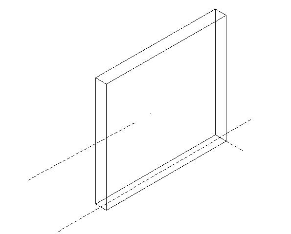
- Enter the first point of the imaginary line to place the form parallel to.
- Enter the end point of the imaginary line.
-
Enter a data point to define the start point of the parallel form.
A line starting from this point and parallel to the imaginary line displays dynamically.
-
Enter a data point to define the end point of the parallel linear form.
This point is projected on the parallel line.
- (Optional) Go back to step 4 to place another parallel linear form.